Preview — seller contact details are pending.
ASCO 7000 SERIES Power Control System
Custom-engineered paralleling switchgear. Configuration depends on the application.
Contact the sellerMore controls
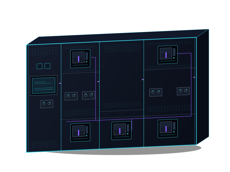
Choose a component
Select a numbered point or open Parts.
Open the official brochureLoading the 3D view. You can read the presentation below.
Introduction
Illustrative sequence and timing. Actual operation depends on the project configuration.
Power fails
Utility power to the facility is lost.
Transfer
Generators start and connect to supply the bus.
Power restored
Priority loads receive power again.
Guided tour
What am I looking at?
See system information in one place.
The touchscreen brings together access to synchronizer and load-share controls, controllers, meters and circuit-breaker information. One-line diagrams show system status.
Interface and equipment configuration depend on the project.
Learn more
The integrated interface combines device information and system visualization alongside the manual controls.
Where are the generator controls?
Find the generator operating controls.
Generator control sections include manual controls for engine-generator testing and selection of operating modes.
The final controls and labels depend on the configured project. This is an explanatory view.
Learn more
Generator control stations provide local manual testing controls alongside the system’s automatic functions.
How are generators connected to the system?
Explore a visible breaker location.
Generator paralleling breakers connect generators to the common bus within the configured operating sequence.
The highlighted exterior face is an explanatory location. Its rating and assigned circuit must be confirmed from project drawings.
Learn more
The PCS combines breaker operation with synchronization and load management as part of the system sequence.
- First connection to an unenergized bus
The cited learning example connects one generator first to an unenergized bus. Other generators synchronize before connecting to the energized bus.
Illustrative sequence. Controls and configuration depend on the project; pictured circuit assignments require confirmation.
Official source · slide 8- Illustrative draw-out view
The cited low-voltage guide describes draw-out generator breakers with connected, test and disconnected positions.
Explanatory movement of exterior representations. Confirm installed devices, mechanism travel and project details from the project documentation.
Official source · pp. 7–8
How is power connected?
Follow the shared power path.
The bus connects source and load circuits. The product family offers several bus configurations to suit the application.
The painted route is illustrative, not a wiring drawing. Bus ratings and segmentation depend on the configured project.
Learn more
Available bus arrangements provide different source and load connection paths; selection depends on the facility’s requirements.
What manual controls are available?
Understand the manual paralleling path.
Manual paralleling allows generators to be connected to the main bus if automatic paralleling becomes inoperable.
Hardwired manual paralleling is standard in the low-voltage product family. The arrangement depends on the project.
Learn more
The product family provides manual paralleling alongside automatic operation. This presentation explains the controls; it does not operate equipment.
Choose your next step
Use the left and right arrow keys to rotate, plus and minus to zoom, and Home to return to the overview.
Loading the 3D view. You can continue reading below.
Product evidence
Key Specs
- System voltage
- 600 V maximum
Low-voltage models.
Official source · p. 11, low-voltage column - Generator capacity
- Up to 32 generators
Available product-family capability; project configuration varies.
Official source · pp. 2, 11 - Load control
- Up to 128 transfer switches and/or circuit breakers
Transfer switches are external controlled equipment.
Official source · pp. 2, 5, 11 - Main bus
- Available up to 10,000 A
Configured product-family rating.
Official source · p. 11, low-voltage column - Bus bracing
- Up to 200 kA
Bus bracing level; not a circuit-breaker interrupting rating.
Official source · p. 11, low-voltage column
Standards and sources
- Switchgear construction
- UL 1558
Standard low-voltage construction.
Official source · p. 11, low-voltage column - Construction option
- UL 891
Optional low-voltage construction.
Official source · p. 11, low-voltage column
ASCO 7000 SERIES Power Control Systems
PS-BR-7000PCS · 2023 R2
View the official document listing
Open the official brochurePDF · English
Let’s discuss your project
Seller contact details have not been added yet. Please return after they are confirmed.